Service Bulletin: How to Replace Meat Probe Sockets on LCHR Units (Z-600-6113 & Z-500-3032)
A Step-by-Step Guide to Replacing Meat Probe Sockets on LCHR Units. Over time, meat probe sockets on LCHR units may experience wear or become faulty, affecting temperature accuracy and performance. To ensure your unit operates at its best, FWE has provided a step-by-step guide for replacing and recalibrating probe sockets. In this post, we’ll walk you through the key points of the replacement process, ensuring your equipment stays accurate, efficient, and ready for service.
Priority Service Notes:
- Be sure to take note of wire locations for each socket. (Fig 1.)
- To unmount sockets, remove the screws as noted in (Fig 2 A & B)
- Clean all existing silicone from the socket mount. (Fig 3)
- Make sure all sockets are properly sealed.
- Ensure correct orientation of sockets when installed. (Fig 4)
Tools Used in this Tutorial
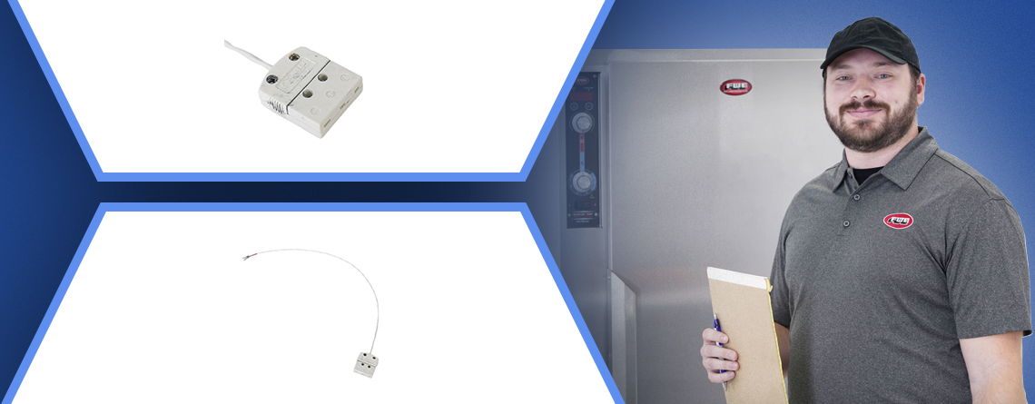
- Replacement Probe Socket (FWE Part # Z-600-6113)
- Small Flathead Screwdriver
- Phillips Screwdriver
- Digital Thermometer (for calibration verification)
Detailed Installation Instructions
- Power the unit on and locate the gears icon in the bottom right corner and press it.
- On the enter PIN screen, enter 4393, then press the green check box.
- On the next screen, you will see a calibration box. Press it.
- Get a glass of ice water and a known working meat probe for testing.
- Insert the meat probe into the far-left socket port #1 on the unit and the other end into ice water. (FIG. 7)
- On the screen, verify P1 meat probe reading.
- A. It should be between 34-38 degrees for a correct reading.
- B. Any temperature above or below that range, contact factory 800-222-4393 option 3.
- Repeat steps 5 and 6 for the 3 remaining probe sockets.
- Once faulty probe sockets have been identified and confirmed, turn the unit off.
- Unplug the unit from the power source.
- Remove the top from the unit.
- Locate faulty probe sockets inside the top of the unit. (FIG 1)
- To remove faulty probe sockets, remove the 2 screws holding it in place. (FIG 2)
- Pull out the faulty probe socket, being careful not to let any debris fall into the unit’s cavity. (FIG 3)
- Clean off any old silicone around the probe socket mounting area. (FIG 4)
- Follow the wires back to the control board, taking close notes of where and how they are connected. (FIG 5)
- Remove wires from the control board. (FIG 6)
- Locate the new probe socket and wire to the control board the same way the previous one was.
- Mount probe socket to unit using screws removed in step 12.
- Silicone around the probe socket to ensure it is fully sealed so no cavity vapors can get into the control area.
- Repeat steps 11-19 for any other faulty probe sockets identified in step 6.
- Once all faulty probe sockets have been replaced, plug the unit back in.
- Repeat steps 1-7 and confirm all probe sockets now read within the correct range.
- Once the unit passes all tests, turn the unit off and remove all testing equipment.
- Replace the top cover and return the unit to normal operation.
* NOTE: Please reference the Instructional PDF to view diagrams and FIGs
Need Assistance?
If you need further guidance or replacement parts, contact FWE’s support team at 1-615-805-3270 or [email protected] for personalized help. Your success is our priority, and we’re just a call or email away.